I selected the Touch Revolution Fusion F07A-0102 capacitive touch display to work with the A20.
It’s not a drop in replacement hardware wise so I’ve built a custom PCB to connect to the A20 LCD connector. In theory this will work with any of the Olinuxino boards that use the same LCD connector. There is a separate connector for the touch as the existing LCD connector does not have the required I2C interface. In fact, I developed this on Android but there is no reason it won’t work with Linux using the same driver changes.
Out of the box, the display part works without any changes to the build if you already have it configured for the Olimex A13 7″ LCD. It is however much brighter due mainly to the fact that there is less light being lost through the touch panel as you do with resistive panels.
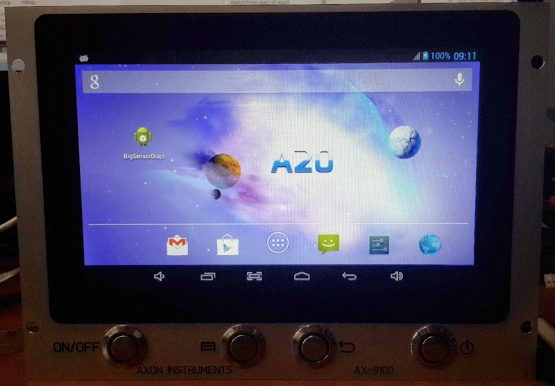
F07A-0102 LCD running with A20.
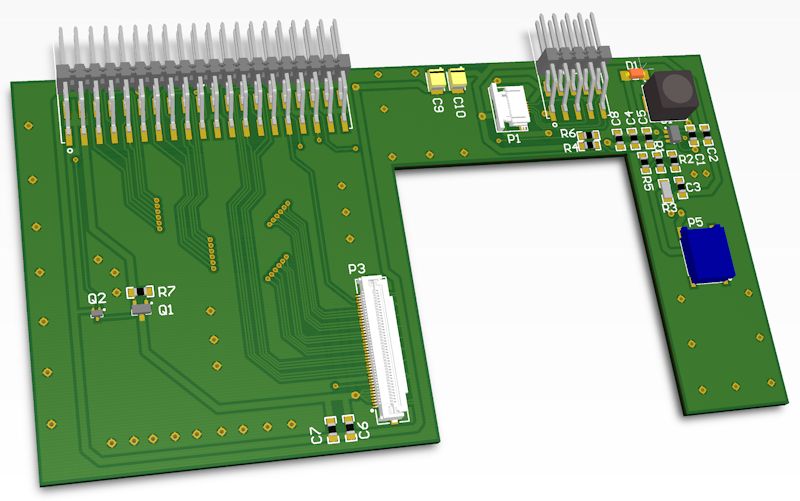
PCB for F07A-0102 Cap LCD
The PCB can be fitted with horizontal or vertical connectors. I chose the Samtec horizontal ones as I have no clearance in the enclosure to mount a vertical connector.
For the touch there is a bit of work to add the driver that is supplied by Touch Revolution as it requires changes to work with the AllWinner drivers.
First job was to add the driver to the code and compile it as a module. You just need to follow the Touch Revolution manual for this ignoring the second bit about adding the board modules. These don’t exist in the AllWinner system due to the sys_config.fex configuration method used.
To add this to the Linux kernel as a module, cd in to the linux3.4 directory and type in the following:
make ARCH=arm menuconfig
Navigate down to the drivers entry and then locate sw_touchscreen. In there select the Fusion_F0710A and set if for <m> for module.
Now exit this and save and cd .. back to the lichee directory. Now do the normal build on this with ./build.sh -psun7i_android
Once this builds check that there is a fusion_F0710a.ko file in the linux3.4/output/lib/modules directory and if there is, it is time to make the changes so that it will work with the A20.
Download the following file and drop it in the directory below, over writing the existing file.
fusion_F0710A.c
/linux-3.4/drivers/input/sw_touchscreen
Open the sysconfig.fex file for the board and edit the ctp_para section as follows. Also, make sure that ctp_detect_use in the ctp_list_para section is set for 0 (no detection)
; ctp_int_port EINT12 on PI16 (SPI1_CS0)
; ctp_twi_id TWI2 (dev) TWI0 (release)
[ctp_para]
ctp_used = 1
ctp_name = "fusion_F0710A"
ctp_twi_id = 1
ctp_twi_addr = 0x10
ctp_screen_max_x = 800
ctp_screen_max_y = 480
ctp_revert_x_flag = 1
ctp_revert_y_flag = 0
ctp_exchange_x_y_flag = 0
ctp_int_port = port:PI16<0><1><default><default>
ctp_wakeup = port:PB13<1><default><default><default>
The ctp_wakeup is not actually used on the first build but I found that leaving this blank caused the system to fail bootup so I set this to an unused GPIO pin. I’ll be enabling this in the new boards and it will use the SPI1_CLK line for this. SPI it not used with the Android build. As the fex file allows configuration, you can move it to any I2C and IO pins. I’ll be moving this to I2C-0 on the final hardware but using I2C-1 for testing via the UEXT connector.
Make sure that the resistive settings are set for used as off.
[rtp_para]
rtp_used = 0
Then you need to edit the init.sun7i.rc file in the Android build. We need to display the current resistive panel. Locate this line and put a # at the start of it or simply delete this line altogether.
# insmod /system/vendor/modules/sunxi-ts.ko
We don’t need to INSMOD our Fusion driver as the kernel will do this when it detects the ctp panel in the settings when init_input is run. We need though to add our panel to the detection list. Not sure this is actually needed but I added it anyway. Locate the file sw_device.c in linux-3.4/drivers/input and edit it to add this line to the ctps[] structure. Just add it to the end of the existing list.
{"fusion_F0710A", { 0x10}, 0x0D, {0x00 }, 0},
The Touch Revolution document refers to changing the name of the qwert.idc file to fusion0710A.idc and copying this to the platform. What I did was create a copy of this file and then in the olinuxino_a20.mk file I added this line to the PRODUCT_COPY_FILES entry. You can put this at the end of the list and put a \ on the line above or do as I did and insert the line below above the last entry.
device/softwinner/olinuxino-a20/fusion0710A.idc:system/usr/idc/fusion0710A.idc \
GPIO Driver
One last change needed is to fix the GPIO interrupt driver as I found that it was outputing an error each time I touched the screen. It shouldn’t be as the interrupt was being handled correctly and passing back the correct IRQ_HANDLED flag. This fix will stop it from doing this.
Locate the file gpio_eint.c in the following directory:
linux-3.4/arch/arm/mach-sun7i/gpio
Edit the function right at the end called gpio_irq_hdl. The following line needs to be changed.
if (pdev_id->handler(pdev_id->parg)) {
to this
if (pdev_id->handler(pdev_id->parg) != IRQ_HANDLED) {
IRQ_HANDLED is defined as (1<<0) so when the IRQ handler for the screen returns this line would always be true and show a failed handler. This in fact would be incorrect.
If you build the code now it will support touch.
As of March 22nd I’ve not been able to get pinch to zoom working and the driver does appear to send 2 touch commands to the kernel so not sure what’s wrong yet. Still working on this.
UPDATE – TOUCH FIXED
As of 27th March, I have made a couple of small changes that fix and issue where I could not swipe down from the task bar. It’s caused by legacy resistive touch support still on the system and this was causing incorrect position data to be sent to the kernel.
If your system has the pointercal file in the data directory from previous use of a resistive touch panel, delete this file and change the sys_config.fex file to remove the invert on the X position. Rebuild and deploy the updated build and you will now have a fully working touch with pull down from the task bar.
10″ Support
The 10″ panel from Touch Revolution has the same I2C for the touch and should work with this same code. There will be changes needed for the LCD as the 10″ LCD uses LVDS but as the A20 is configurable for LVDS it remains only to configure the output and create a suitable PCB for it. The current PCB shape is not suitable for the 10″ panel.

Hey great work what i’ve senn so far from you.
can i contact you somehow i think i need yout help
Sven
Hello Dave,
Is there any chance that you sell one touchscreen + adapter PCB?
Hi Ion, Sadly that LCD has been discontinued by the manufacturer.I only have 1 left in stock and I need to keep this as a spare for the units still in operation.
I have re-engineered a replacement using the Newhaven NHD7.0 LCD and I have also engineered an LVDS interface between the LCD and the A20 to allow a longer cable and stop the issue of flickering due to the clock being corrupted.
Hi, is the new LCD for sale?
Hi Ion, drop me an email to dave@axoninstruments.biz and we can discuss offline.